How to Trim New Wall Construction With 1 Continuous Rigid Insulation Sheathing
Rigid Foam Insulation for Existing Exterior Walls
Scope
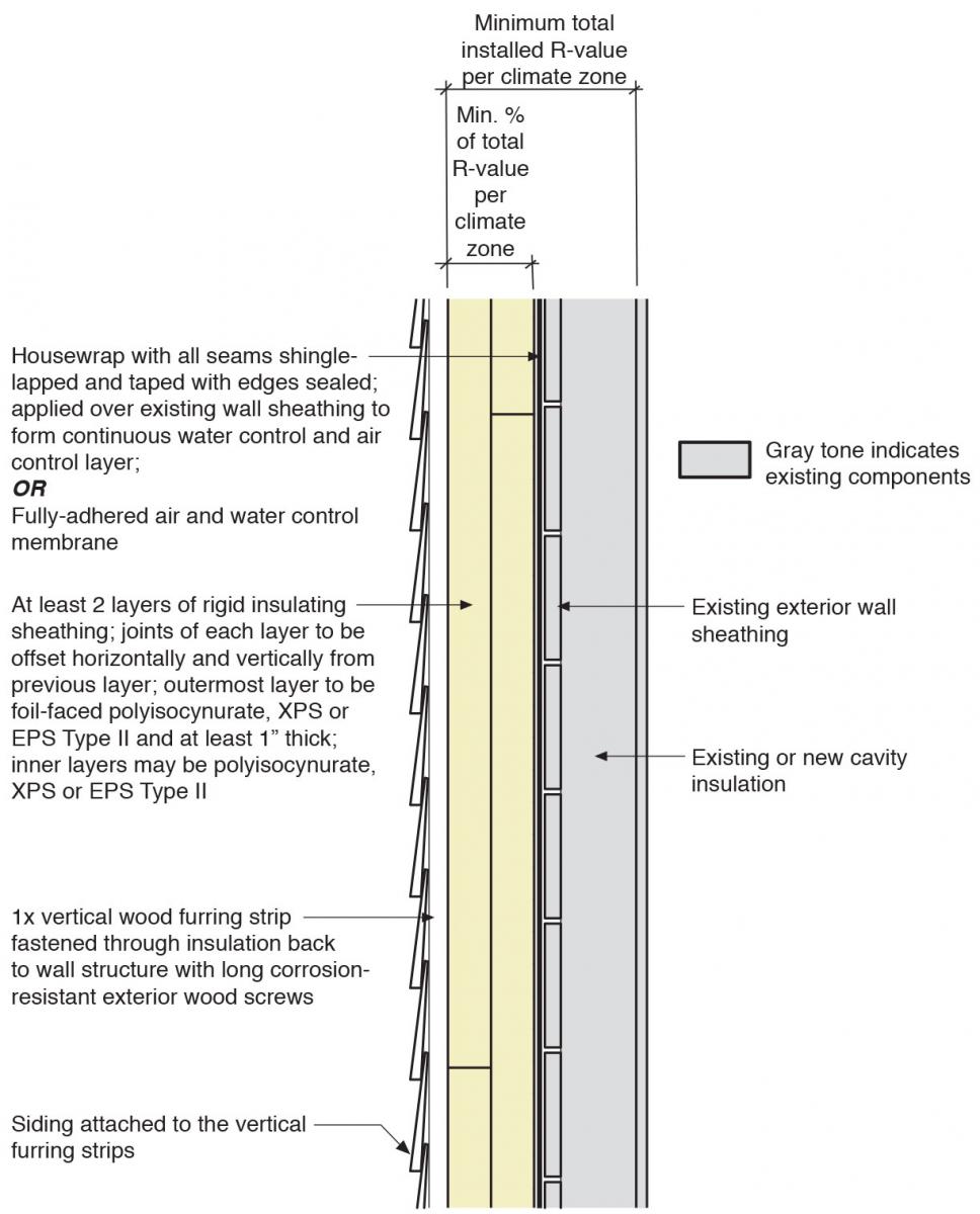
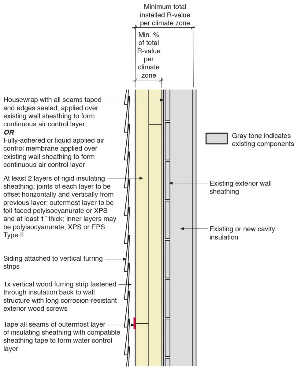
In this retrofit wall assembly, the air control layer is applied directly over the existing wall sheathing and then covered by at least two layers of insulating sheathing held in place by vertical furring strips. The vertical furring strips also provide the means of attachment for the exterior siding.
There are two possible locations for the water control layer for this retrofit wall assembly – at the outer face of the insulating sheathing or between the insulating sheathing and the existing exterior wall.
Insulate the walls of an existing home by removing the existing cladding and installing rigid foam insulating sheathing to upgrade the major building enclosure functions of the wall – water control, air control, vapor control, and thermal control, as follows:
- Remove existing wall cladding and trim.
- Prepare the wall sheathing for air/water control membrane.
- Remove windows and doors as needed to allow flashing of openings and air control transitions into openings.
- Install a continuous air/water control layer to the original sheathing or to the insulation sheathing.
- Transition the wall air/water control membrane to adjacent assemblies.
- Install flashings and air control transitions.
- Re-install windows and doors or install new windows and doors in properly flashed openings.
- Install insulating sheathing in accordance with code to satisfy the high R-value performance target for the assembly and for adequate condensation control.
- Install furring strips over insulating sheathing and attach to structure (structural sheathing and/or framing) through insulating sheathing. Install furring strips in a vertical orientation only.
- Install wall cladding and trim, by attaching to the furring strips.
See the Compliance Tab for related codes and standards requirements, and criteria to meet national programs such as DOE's Zero Energy Ready Home program, ENERGY STAR Certified Homes, and EPA Indoor airPLUS.
Description
One method for increasing the insulation level of the walls in existing homes is to remove the exterior cladding and install rigid foam insulation, possibly new house wrap, and new exterior cladding over the walls. This step not only increases the wall R-value, it can also greatly improve the performance of the walls to control the movement of air, vapor, and water through the walls.
Some advantages to this retrofit approach include minimizing the impact of the wall retrofit on the interior finishes of the existing house, supporting continuity of the water and air control layers, reducing thermal bridging or heat transfer through wall framing, and lowering the risk of water damage and condensation within the existing wall structure.
In Figures 1 and 2, the wall siding is represented as lap siding, which could be wood, vinyl, or fiber cement lap siding. Other types of siding that can be attached using the vertical furring strips may be used as well, provided the weight of the siding is less than 10 lb/sf.
Taped insulating sheathing may serve as a layer to control water, air, and heat loss. However, house wrap or a paint-on membrane could also be applied to the original sheathing before the insulating sheathing is installed.
The insulating sheathing is held in place by vertical furring strips, along with other attachments per manufacturer's instructions. The vertical furring strips also provide the means of attachment for the exterior siding and provide a ventilation gap under the siding.
The house wrap should be overlapped and taped at all seams and attached with fasteners per the manufacturer's instructions. (See Figure 2.) If more than one layer of foam is used, the exterior layer of the foam is the water control layer and all seams in that layer should be taped with appropriate foam-compatible tape. The exterior foam layer should be foil-faced polyisocyanurate or XPS and the layer should be at least 1 inch thick. EPS should not be used as the outer layer but EPS Type II could be used as the inner layer. If the exterior of the rigid foam serves as the water control layer, the air control layer would still be house wrap or paint-on membrane that is installed between the existing house sheathing and the rigid foam.
The location of the water control layer has implications for how the water control function is handled at transitions and interruptions. For example, in window installations, if the water control layer is over the existing sheathing, the windows are installed within the existing wall framing. If the water control layer is at the face of the insulating sheathing, the windows are installed within the insulating sheathing layer of the wall, in order to integrate the window flashing into the water control layer.
When installing this retrofit wall assembly, it is recommended that multiple layers of insulating sheathing be applied to the exterior of the existing wall. For example, rather than installing one 2-inch layer of rigid foam, two 1-inch layers are installed. This creates a vapor impermeable layer on the exterior of the existing wall. If there is a wetting event (e.g., a plumbing leak) that causes the existing wall structure to become wet, it is important that the wall is able to dry to the inside. To allow drying to the inside, any new or existing application of closed-cell spray foam in the wall cavities should be limited to a thickness of no more than one inch. For other types of spray foam insulation, the vapor permeance of the installed thickness must be at least 1.0 perm. Open-cell spray foam insulation meets this criteria for typical framed wall cavity depths. This may not be the case for some medium-density spray foams.
It is advisable to avoid use of an interior vapor barrier and vapor impermeable wall coverings such as non-latex paint and vinyl wallpapers with this retrofit wall approach because these limit the drying potential to the interior. These types of wall coverings may contribute to problems if the interior space has high humidity, there is a history of water leakage in the wall, or the exterior wall has gotten wet during construction.
How to Install Rigid Foam Board Insulation at Exterior Wall
- Remove the existing wall cladding and trim, and inspect the structural integrity of the wall. Check the wall framing for any deficiencies, rot, insect damage, etc. Based on the findings of the inspection, revise the wall assembly plans and review specific detailing as needed. Proceed only after needed repairs are performed. Meet or exceed the minimum requirements of the current adopted building and energy codes.
- Prepare the wall sheathing to receive the air/water control membrane or house wrap, if one is going to be used. Appropriate preparation of the wall sheathing will depend upon the nature of the existing sheathing and the air control strategy pursued. If using a sheet good (house wrap) as the air/water control layer, all protruding fasteners must be removed to avoid punctures or tears in the membrane. Gaps or voids in the sheathing layer may need to be filled in. Use a primer for self-adhered membranes if recommended by the membrane manufacturer if installing membrane.
- Remove windows and doors and trim to allow for proper flashing of the window and door openings, and to permit the installation of air control transition membranes.
- Install a continuous air control membrane (house wrap or paint-on membrane) over the existing sheathing as shown in Figure 1. Connect the air control membrane to the air control layer of adjacent assemblies in a tight and durable manner. Seal all penetrations against air and water leaks. This layer may also serve as the water control layer, or the surface of the rigid foam can serve as the water control layer if all seams are sealed, as shown in Figure 2.
- Install flashings and air control transitions. Transition the air control at the top and bottom margins of the exterior wall into the window and door rough openings and air seal all penetrations through the wall. Flash window and door rough openings as well as all wall penetrations.
- Re-install windows and doors or install new windows and doors in properly flashed openings. If the water control layer is over the existing sheathing, the windows are installed within the existing wall framing whereas if the water control layer is at the face of the insulating sheathing, the windows are installed within the insulating sheathing layer of the wall. This is to ensure the window flashing is properly integrated into the water control layer. Air seal the window and door units to the air control transition membranes at the interior perimeter of the window and door units.
- Install insulating sheathing over the air/water control membrane. Butt joints tight. When installing multiple layers, offset seams in two directions. If the surface of the rigid foam will serve as the water control layer, then the exterior layer of rigid foam cannot be EPS, it must be foil-faced polyisocyanurate or XPS and all seams of the exterior foam layer must be taped. Until furring strips are installed, insulating sheathing pieces can be held in place with cap nails or screws with roofing washers.
- Install furring strips over insulating sheathing and attach furring strips to the wall structure (structural sheathing and/or framing) through the insulating sheathing. Install furring strips in a vertical orientation only. It is important to install furring strips in a vertical, not horizontal, orientation to allow drainage behind the cladding/trim and to prevent water from dwelling within the system. 1x4 furring is recommended. The furring need not be preservative treated for moisture protection. The spacing of fasteners through the furring strips must be such that the cladding load is distributed to no more than 10 lb per fastener.
- Attach cladding and trim to the vertical furring strips.
Ensuring Success
Refer to the current adopted building and energy codes for information on appropriate levels of insulation for the different climate zones as well as the proper ratios of vapor and air impermeable and permeable insulation.
Remediate any hazardous conditions that will be affected (e.g., exposed or aggravated) by the planned work. Follow applicable laws and industry procedures for mitigation of hazardous materials. Engage the services of a qualified professional when needed.
Given the increased airtightness associated with this retrofit, combustion safety testing and controlled mechanical ventilation upgrades are required to maintain acceptable indoor air quality.
Climate
The exterior wall assembly should be designed for the specific hygrothermal region, rain exposure zone, and interior climate where the home is located.
The map in Figure 1 shows the climate zones for states that have adopted energy codes equivalent to the International Energy Conservation Code (IECC) 2009, 12, 15, and 18. The map in Figure 2 shows the climate zones for states that have adopted energy codes equivalent to the IECC 2021. Climate zone-specific requirements specified in the IECC are shown in the Compliance Tab of this guide.
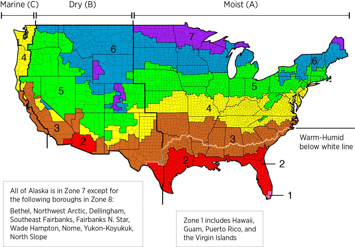
Figure 2. Climate Zone Map from IECC 2009, 12, 15, and 18. (Source: 2012 IECC)
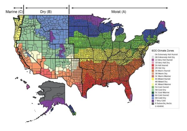
Figure 2. Climate Zone Map from IECC 2021. (Source: 2021 IECC)
Cold Climates
The insulation levels should be based on the minimum requirements for vapor control in the current adopted building code and the minimum requirements for thermal control in the current energy code. Additional insulation can be added above these minimums to create high R-Value exterior wall assemblies. The minimum insulation requirements for ceilings, walls, floors, and foundations in new homes, as listed in the 2009, 2012, 2015, 2018, and 2021 IECC and IRC, can be found in this table.
High Wind Zones
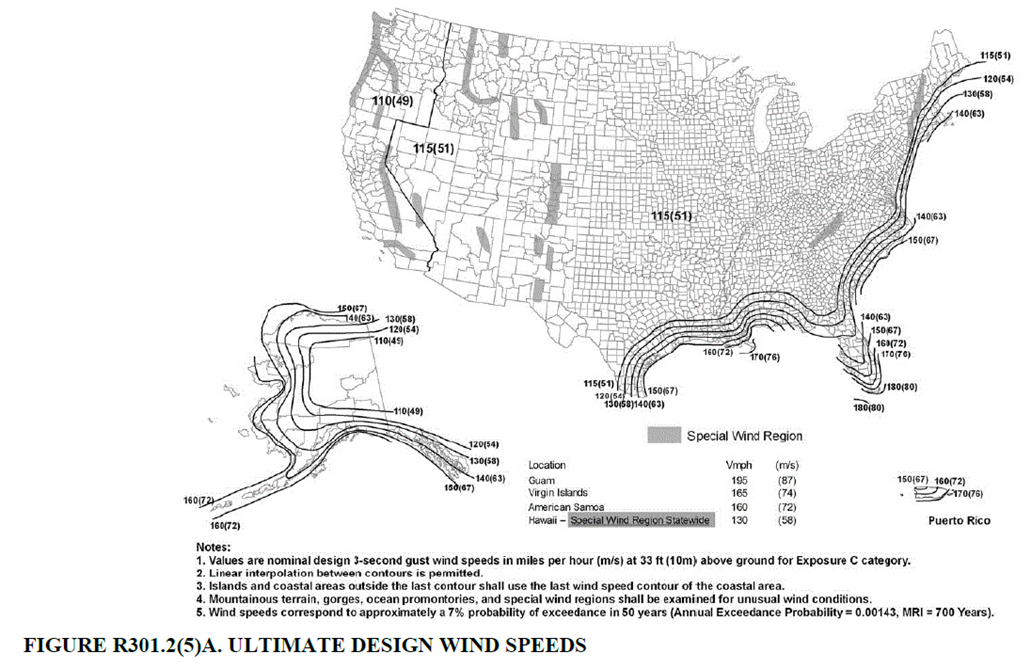
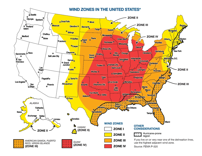
If your home is located in one of the designated high-wind zones shown in Figure 3 and Figure 4, ensure that siding is wind resistant to minimize the risk of damage to the rigid foam sheathing layer.
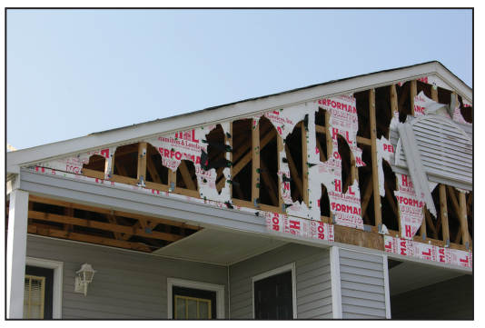
Rigid foam should not be used as the sole sheathing material in gable end walls in high-wind areas; it should be supported by plywood or OSB. In the house shown in Figure 5, the vinyl siding at the gable end wall was installed over plastic foam insulation with no plywood or OSB wood sheathing behind it. The foam insulation and vinyl siding alone were not able to withstand wind pressures which caused the wall to fail allowing wind-driven rain to freely enter the attic and saturate the ceiling insulation, causing collapse of the ceiling.
Wildfire Prone Areas
With limited exceptions, International Building Code Section 2603.5.5, Vertical and lateral fire propagation, requires wall assemblies in Type I, II, III and IV construction using foam plastic insulation to pass the National Fire Protection Association (NFPA) 285 testing requirements. Despite stating "non-load bearing" in its title and scope, NFPA 285 applies to both non-load bearing and load-bearing walls. There are many polyiso, EPS, and XPS rigid foam products that have passed the NFPA 285 wall assembly test for fire resistance; some fireproofing installation details may be required. Consult the manufacturers' instructions (Walls & Ceilings 2017).
See the Solution Center guide "Wind and Disaster Resistant Siding" for more information.
The Compliance tab contains both program and code information. Code language is excerpted and summarized below. For exact code language, refer to the applicable code, which may require purchase from the publisher. While we continually update our database, links may have changed since posting. Please contact our webmaster if you find broken links.
ENERGY STAR Certified Homes, Version 3/3.1 (Rev. 09)
ENERGY STAR Certified Homes requires that ceiling, wall, floor, and slab insulation levels meet or exceed those specified in the 2009 International Energy Conservation Code (IECC) with some alternatives and exceptions, and achieve Grade 1 installation per RESNET Standards (see 2009 and 2012 IECC Code Level Insulation – ENERGY STAR Requirements and Insulation Installation (RESNET Grade 1). If the state or local residential building energy code requires higher insulation levels than those specified in the 2009 IECC, you must meet or exceed the locally mandated requirements. Some states have adopted the 2012 or 2015 IECC. Visit the U.S. DOE Building Energy Codes Program to see what code has been adopted in each state.
Rater Design Review Checklist
3. High-Performance Insulation.
3.1 Specified ceiling, wall, floor, and slab insulation levels comply with one of the following options:
3.1.1 Meets or exceeds 2009 IECC levels4, 5, 6OR;
3.1.2 Achieves ≤ 133% of the total UA resulting from the U-factors in 2009 IECC Table 402.1.3, per guidance in Footnote 4d, AND specified home infiltration does not exceed the following:5, 6
- 3 ACH50 in CZs 1, 2
- 2.5 ACH50 in CZs 3, 4
- 2 ACH50 in CZs 5, 6, 7
- 1.5 ACH50 in CZ 8
Rater Field Checklist
Thermal Enclosure System
1. High-Performance Fenestration & Insulation.
1.3 All insulation achieves Grade I install. per ANSI / RESNET / ICC Std. 301. Alternatives in Footnote 4.4, 5
Footnote 4) Two alternatives are provided: a) Grade II cavity insulation is permitted to be used for assemblies that contain a layer of continuous, air impermeable insulation ≥ R-3 in Climate Zones 1 to 4, ≥ R-5 in Climate Zones 5 to 8; b) Grade II batts are permitted to be used in floors if they fill the full depth of the floor cavity, even when compression occurs due to excess insulation, as long as the R-value of the batts has been appropriately assessed based on manufacturer guidance and the only defect preventing the insulation from achieving Grade I is the compression caused by the excess insulation.
Foontote 5) Ensure compliance with this requirement using the version of ANSI / RESNET / ICC Std. 301 utilized by RESNET for HERS ratings.
2. Fully-Aligned Air Barriers.6 At each insulated location below, a complete air barrier is provided that is fully aligned as follows:
Ceilings: At interior or exterior horizontal surface of ceiling insulation in Climate Zones 1-3; at interior horizontal surface of ceiling insulation in Climate Zones 4-8. Also, at exterior vertical surface of ceiling insulation in all climate zones (e.g., using a wind baffle that extends to the full height of the insulation in every bay or a tabbed baffle in each bay with a soffit vent that prevents wind washing in adjacent bays).7
Walls: At exterior vertical surface of wall insulation in all climate zones; also at interior vertical surface of wall insulation in Climate Zones 4-8.8
Floors: At exterior vertical surface of floor insulation in all climate zones and, if over unconditioned space, also at interior horizontal surface including supports to ensure alignment. Alternatives in Footnotes 11 & 12.10, 11, 12
2.7 All other floors adjoining unconditioned space (e.g., rim / band joists at exterior wall or at porch roof)
3. Reduced Thermal Bridging.
3.4 At above-grade walls separating conditioned from unconditioned space, one of the following options used (rim / band joists exempted):16
3.4.1 Continuous rigid insulation, insulated siding, or combination of the two is: ≥ R-3 in CZ 1-4; ≥ R-5 in CZ 5-8 OR;17, 18, 19
3.4.2 Structural Insulated Panels OR; Insulated Concrete Forms OR; Double-wall framing OR;17,20
3.4.3 Advanced framing, including all of the Items below:21
3.4.3a Corners insulated ≥ R-6 to edge22, AND;
3.4.3b Headers above windows & doors insulated ≥ R-3 for 2x4 framing or equivalent cavity width, and ≥ R-5 for all other assemblies (e.g., with 2x6 framing)23, AND;
3.4.3c Framing limited at all windows & doors to one pair of king studs, plus one pair of jack studs per window opening to support the header and sill, AND;
3.4.3d Interior / exterior wall intersections insulated to same R-value as rest of exterior wall,24AND;
3.4.3e Minimum stud spacing of 16 in. o.c. for 2x4 framing in all Climate Zones and, in CZ 6-8, 24 in. o.c. for 2x6 framing.25
4. Air Sealing (Unless otherwise noted below, "sealed" indicates the use of caulk, foam, or equivalent material).
4.1 Ducts, flues, shafts, plumbing, piping, wiring, exhaust fans, & other penetrations to unconditioned space sealed, with blocking / flashing as needed.
Footnote 6) For purposes of this Checklist, an air barrier is defined as any durable solid material that blocks air flow between conditioned space and unconditioned space, including necessary sealing to block excessive air flow at edges and seams and adequate support to resist positive and negative pressures without displacement or damage. EPA recommends, but does not require, rigid air barriers. Open-cell or closed-cell foam shall have a finished thickness ≥ 5.5 in. or 1.5 in., respectively, to qualify as an air barrier unless the manufacturer indicates otherwise. If flexible air barriers such as house wrap are used, they shall be fully sealed at all seams and edges and supported using fasteners with caps or heads ≥ 1 in. diameter unless otherwise indicated by the manufacturer. Flexible air barriers shall not be made of kraft paper, paper-based products, or other materials that are easily torn. If polyethylene is used, its thickness shall be ≥ 6 mil.
Footnote 8) All insulated vertical surfaces are considered walls (e.g., above and below grade exterior walls, knee walls) and must meet the air barrier requirements for walls. The following exceptions apply: air barriers recommended, but not required, in adiabatic walls in multifamily dwellings; and, in Climate Zones 4 through 8, an air barrier at the interior vertical surface of insulation is recommended but not required in basement walls or crawlspace walls. For the purpose of these exceptions, a basement or crawlspace is a space for which ≥ 40% of the total gross wall area is below-grade.
Water Management System Builder Requirements
2 Water-Managed Wall Assembly.
2.1 Flashing at bottom of exterior walls with weep holes included for masonry veneer and weep screed for stucco cladding systems, or equivalent drainage system.9
2.2 Fully sealed continuous drainage plane behind exterior cladding that laps over flashing in Item 2.1 and fully sealed at all penetrations. Additional bond-break drainage plane layer provided behind all stucco and non-structural masonry cladding wall assemblies.9, 10
2.3 Window and door openings fully flashed.11
Footnote 9) These Items not required for existing structural masonry walls (e.g., in a home undergoing a gut rehabilitation). Note this exemption does not extend to existing wall assemblies with masonry veneers.
Footnote 10) Any of the following systems may be used: a monolithic weather-resistant barrier (i.e., house wrap) shingled at horizontal joints and sealed or taped at all joints; weather resistant sheathings (e.g., faced rigid insulation) fully taped at all butt joints; lapped shingle-style building paper or felts; or other water-resistive barrier recognized by ICC-ES or other accredited agency.
Footnote 11) Apply pan flashing over the rough sill framing, inclusive of the corners of the sill framing; side flashing that extends over pan flashing; and top flashing that extends over side flashing or equivalent details for structural masonry walls or structural concrete walls.
Please see the ENERGY STAR Certified Homes Implementation Timeline for the program version and revision currently applicable in in your state.
DOE Zero Energy Ready Home (Revision 07)
The DOE Zero Energy Ready Home Program is a voluntary high-performance home labeling program for new homes operated by the U.S. Department of Energy. Builders and remodelers who are conducting retrofits are welcome to seek certification for existing homes through this voluntary program.
Exhibit 1 Mandatory Requirements.
Exhibit 1, Item 1) Certified under the ENERGY STAR Qualified Homes Program or the ENERGY STAR Multifamily New Construction Program.
Exhibit 2, Item 2) Ceiling, wall, floor, and slab insulation shall meet or exceed 2015 IECC levels and achieve Grade 1 installation, per RESNET standards.
2009-2021 IECC and IRC Insulation Requirements Table
The minimum insulation requirements for ceilings, walls, floors, and foundations in new homes, as listed in the 2009, 2012, 2015, 2018, and 2021 IECC and IRC, can be found in this table.
2009, 2012, 2015, 2018, and 2021 International Energy Conservation Code (IECC)
Section R401.3 Certificate
Section R402.1.2 (402.1.1 in 2012 and 2009 IECC) Insulation and fenestration criteria and requirements by component
Table R402.1.2 (402.1.4 in 2009 and 2015 and 402.1.3 in 2009 and 2012 IECC) Equivalent U-factors
Section R402.4 Air leakage (Mandatory)
Table R402.4.1.1 (402.4.2 in 2009 IECC) Air barrier and insulation installation
Retrofit: 2009, 2012, 2015, 2018, and 2021 IECC
Section R101.4.3 (in 2009 and 2012). Additions, alterations, renovations, or repairs shall conform to the provisions of this code, without requiring the unaltered portions of the existing building to comply with this code. (See code for additional requirements and exceptions.)
Chapter 5 (in 2015, 2018, 2020). The provisions of this chapter shall control the alteration, repair, addition, and change of occupancy of existing buildings and structures.
2012 and 2009 International Residential Code (IRC)
Section R302.1 Exterior walls
Table R302.1 Exterior walls
Section R302.10 Flame spread index and smoke developed index for insulation
Section R316 Foam plastic
Section R403.3.4 Termite damage
Section R703 Exterior covering.
Section R703.11.2 Foam plastic sheathing
Section N1101.12.1 (N1101.4 in 2009 IECC) Building thermal envelope insulation
Section N1101.12.4 (N1101.6 in 2009 IECC) Insulation product rating
Section N1101.16 (N1101.9 in 2009 IECC) Certificate (Mandatory)
Section and Table N1102.1.1 (N1102.1 in 2009 IECC) Insulation and fenestration criteria and requirements by component
Table N1102.1.1 Insulation and fenestration requirements by component
Table N1102.1.3 (N1102.1.2 in 2009 IECC) Equivalent U-factors
Section N1102.4 Air leakage (Mandatory)
Table N1102.4.1.1 (N1102.4.2 in 2009 IECC) Air barrier and insulation installation/inspection
2015, 2018, and 2021 IRC
Section R302.1 Exterior walls
Table R302.1 Exterior walls
Section R302.10 Flame spread index and smoke developed index for insulation
Section R316 Foam plastic
Section R403.3.4 Termite protection
Section R703 Exterior covering.
Section R703.11.2 Foam plastic sheathing (Insulation over foam plastic sheathing in 2018 and 2021 IRC)
Section N1101.10.1 (R303.1.1) Building thermal envelope insulation
Section N1101.10.4 (R303.1.4) Insulation product rating
Section N1101.14 (R401.3) Certificate (Mandatory)
Section N1102.1.2 (R402.1.1) Insulation and fenestration criteria
Table N1102.1.2 (R402.1.1) Insulation and fenestration requirements by component
Table N1102.1.4 (R402.1.4) Equivalent U-factors (R-value computation in 2018 and 2021 IRC)
Section N1102.4 (R402.4) Air leakage (Mandatory)
Table N1102.4.1.1 (R402.4.1.1) Air barrier and insulation installation
Retrofit: 2009, 2012, 2015, 2018, and 2021 IRC
Section R102.7.1 Additions, alterations, or repairs. Additions, alterations, renovations, or repairs shall conform to the provisions of this code, without requiring the unaltered portions of the existing building to comply with the requirements of this code, unless otherwise stated. (See code for additional requirements and exceptions.)
Appendix J regulates the repair, renovation, alteration, and reconstruction of existing buildings and is intended to encourage their continued safe use.
Access to some references may require purchase from the publisher. While we continually update our database, links may have changed since posting. Please contact our webmaster if you find broken links.
References and Resources*
*For non-dated media, such as websites, the date listed is the date accessed.
Contributors to this Guide
The following authors and organizations contributed to the content in this Guide.
Mobile Field Kit
The Building America Field Kit allows you to save items to your profile for review or use on-site.
Sign Up or Log In
Did you find this information helpful?
Source: https://basc.pnnl.gov/resource-guides/rigid-foam-insulation-existing-exterior-walls
0 Response to "How to Trim New Wall Construction With 1 Continuous Rigid Insulation Sheathing"
Post a Comment